ACTIVE AND INDUCTIVE RESISTANCES OF STATOR AND ROTOR WINDING
Calculation of active resistances.Activee resistance of phase of stator winding is calculated, according to a formula (2.3). Resistance r1 is in the heated state
r1 = r1ϑ = r1 200 [1 + 0,004(ϑ + ϑenv − 20°)], (25)
where r1 200 = (wph1∙lar av) / (57Sar∙a1∙a2) − resistance of stator phase at 20°C, Ω; ϑ − the expected overheat of winding, °C; ϑenv − temperature of environment; lar av − average length of loop of armature winding, m.
Active resistance of phase of squirrel-cage rotor in the heated state is (fig. 4.9)
r2 = r2ϑ = (1/p)(rb + rr)[1 + α∙(ϑ + ϑenv − 20°)], (26)
where р − number of poles pair; rb − active resistance of rotor bar (at 20° С); rr − active resistance of s.c. rings (at 20° С); α − temperature coefficient of material resistance of rotor winding.
Active resistance of rotor bar
rb200 = (lb / Sb)∙ρ, (27)
where lb − length of rotor bar, m; Sb – cross-section area of bar, mm2; ρ − specific electric resistance of bar material at 20° С.
For rotors with an aluminium pouring for a slot, represented on a fig. 4.9, c, the area of cross-section of bar is determined by a formula (mm2)
Sb = π(b1 − 0,2)2 / 8 + π(b2 − 0,2)2 / 8 + (b1 + b2 − 0,4)∙h1 / 2 (28) Active resistance of s.c. rings, reduced to the bar (at 20° С),
rr20о = 2π∙Dr / [z2∙Sr∙(2sin π∙p/z2)2]∙ρ, (29)
where Dr − diameter of s.c. ring, m; Sr − area of cross-section of s.c. ring, mm2.
Active resistance of phase of rotor winding, resulted to the stator winding,
r'2 = r2∙krd, (30)
where krd − coefficient of reduction;
krd = (m1/m2) [wph1∙kw1 / (wph2∙ kw2)]2 = 4p∙m1∙wph12kw12 /z2 (31)
At m1 = 3
krd = w2ph1∙k2w1 / (w2ph2∙ k2w2) = 12∙p∙ w2ph1∙k2w1 / z2. (32)
Values of specific resistances ρ and temperature coefficients α for materials, applied for shortcircuited windings, driven to the table.7.
Tabl. 7
| Material | ρ, Ω∙ mm2/m | α | γ |
| Copper M-1 | 0,0175=1/57 | 0,0040 | 8,9 |
| Brass ЛС-59-1 | 0,065 | 0,0026 | 8,5 |
| Brass Л-62 | 0,071 | 0,0017 | 8,5 |
| Aluminium | 0,035=2/57* | − | 2,6 |
* For an aluminium a value ρ takes into account the presence of emptinesses at pouring.
Calculation of inductive resistances.Inductive resistance of stator winding phase (Ω)
Xs1 = [4π∙f1∙w2ph1∙l1 / (p∙q1)] ∑λ1∙10-8 (33)
where q1 = z1/ (2p∙m1)– a number of slots on a pole and phase of stator winding; l1 − active length of stator; f − frequency of network; λ1 − total specific conductivity for the leakage fluxes of stator winding.
Inductive resistance of phase of shortcircuited rotor
Xs2 = (2π∙f1∙l2 /p)∙∑λ2∙10-8(34)
where l2 − active length of rotor; ∑λ2 − total specific conductivity for the leakage fluxes of rotor
∑λ2 = λsl2 + λδ2 + λec2 (35)
where λsl2 − specific conductivity of slot dispersion of rotor; λδ2 − specific conductivity of dissipation in an air-gap; λec2 − specific conductivity of dissipation of end coils.
Specific conductivity of rotor slot dissipation λsl2 equals to:
а) for a round slot (fig. 9, а)
λsl2 = 1,25(0,66 + hlm2 / bg2); (36)
b) for a pyriform slot (fig. 9, b)
λsl2 = 1,25 [(2/3)∙h1/ (b1 + b2) + 0,66 + hlm2 / bg2]; (37)
c) for pyriform closed slot (fig. 9, c)
λsl2 = 1,25 [(2/3)∙h1/ (b1 + b2) + λsb],
where λsb − specific conductivity of leakage fluxes through the bridge of slot, determined graphicaly.
Specific conductivity of dissipation in an air-gap λδ2 for motors with a shortcircuited rotor
λδ2 = tz2/(9,5δ∙kδ) (38)
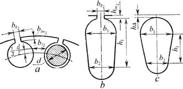
Fig. 9
For motors of very small power with a shortcircuited rotor a specific conductivity A,к2 can be count up by a formula
λδ2 = (tz1 – bg1 − bg2) / (12,8∙δ), (39)
where bg1 and bg2 − width of stator and rotor slot slit respectively.
Specific conductivity of dissipation of end coils of s.c. rotor
λec2 = 2,89Dr / [z2∙l2∙(2sin πρ / z2)2]∙lg2,36 Dr av / (a + b),(40)
where Dr av − average diameter of s.c. ring; (a + b) − half of perimeter of section of s.c. ring.
Inductive resistance of winding phase of s.c. rotor, reduced to the stator winding,
X ‘s2 = Xs2∙krd = Xs2(4p∙m1∙wph12∙kw12) / z2 (41)
5. CHOICE OF EXCITATION CAPACITOR
Total reactive-power of capacitors Рex, required for excitation of three-phase asynchronous generator and compensation of phase-shift of loading,
Рex=Рal∙(tg φG + tg φ), (42)
where Рal − active-power, consumed by load (on three phases); φG, φ − angles of phase-shift between voltage and current of generator and load respectively.
As stated above, for generators of small power (up to 1 kW) a tgφG = 0,5÷0,7, and a power-factor of load usually is within the limits of 0,85÷0,95, i.е. tgφ = 0,3÷0,6.
Thus, necessary power of excitation capacitors is approximately equal to the consumable active-power, i.е.
Рex ≈ Рal (43)
Because power of excitation
Рex = 2π∙f∙Сcb∙Uc2, (44) I" (4.44)
then the capacity of capacitors block diminishes with the increase of frequency and voltage at a capacitor:
Сcb=Рex / (2πfUc2) (45) : (4.45)
However with the increase of operating voltage a mass of capacitors increases, and with the increase of frequency it is necessary to reduce operating voltage because of internal losses growth in capacitor.
For the capacitors of type К75-10, being the best for operating in the alternating current circuits, dependence of mass МC of operating voltage
МC≡kcUop2Сcb (46)
where kc − coefficient of proportionality, g/(V2F).
The value of kc depends on mass of capacitor and is span:
kc =(0,8÷1,2)∙103.
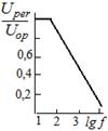 Dependence of permissible voltage Uper at the capacitor is determined by technical requirements. For capacitors К75-10 this dependence can be presented by expression:
Uper / Uop = 1,9÷0,45lg f (47)
The graphic image of this dependence is presented on a fig. 10.
Fig. 10 From(47) it is possible to find expressions for specific mass of capacitors
Мс/Рex = (kс/2π)1/[f (1,9÷0,45lg f)]. (48)
The graphic image of dependence of capacitor specific mass on frequency is presented on a fig. 11. The got result (48) shows that specific mass of capacitors does not depend on voltage and is minimum on frequency 2400 Hz. A circuit of capacitors connection does not import also: a star or triangle − mass of capacitors is identical. It is important only, that capacitors were used at their voltage rating.
return false">ссылка скрыта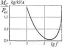 If a generator operates at environment temperature below 70°C, a voltage at capacitor can be increased on 20%, here specific mass of capacitors diminishes yet on 40%.
At star connection of capacitors, when voltage at capacitor equals to phase one Uс Fig. 11 = Uph1 a capacity of capacitors on a phase is
Сλ = [1/(2π∙f∙Uph12)]∙Рex/3. (49)
If capacitors are connected in a triangle, then voltage at them increases in √3 times as compared to voltage at connection of capacitors in a star, and a capacity diminishes in three times
CΔ ={1/[2π∙f∙ (√3∙Uph1)2]}∙Pex/3. (50)
For the optimal use of capasitors at their triangle connection it is necessary to choose them on heightened operating voltage, not to exceed the permissible specific losses and field intensity in the dielectric of capacitor.
At the known design parameters of generator and given voltage and frequency a capacity of capacitors at their star connection equals to:
СY = 1/(ω12∙L1) = 1/ [ω12(X1 + Xm0) / ω1] = 1/ [ω1(X1 + Xm0)], (51) where Xm0 = Еphо/Imо − inductive resistance of magnetizing contour at o.c. of generator (point A on a fig. 1).