ORDER of WORK IMPLEMENTATION
1. To acquaint itself with the experimental plant and write down in report its technical descriptions and metrological data of measuring devices.
2. For research of motor with the parallel excitation to make a chart of fig. 3.6 and set slider of the Rem rheostat in position of minimum resistance, and slider of the Reg and RL rheostats - in position of maximal resistance
3. To close the S1 switch and, smoothly multiplying resistance of the Rem rheostat, toset frequency of the generator G at level 480 Hz and to bring the indications of measuring devices in tabl. 3.1.
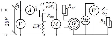
Fig. 3.6
Table 3.1
____________________________________________________ _____Measuring__________________Calculations___________________
V, Iam, Pg, f, Ω, Mo, Mg, M = MO + MG
V A W Hz 1/s N-m N-m N-m
To calculate angular frequencyof rotor rotation by the formula of Ω = 2πf, 1/s. Anti-torque moment at open circuit to calculate by formula

where Іar0 – armature current at open circuit of G generator, revolved by motor, that is, when the S2 switch turned off, and frequency is equal to 480 Hz.
In future to consider the value of the Mo moment constant.
Anti-torque moment, created by generator, calculate by formula

Resulting anti-torque moment of motor M isequal to: M = Mo + Mg.
4. To close the S2 switch and by the Reg rheostat, decreasing its resistance, to load an motor while frequency of current will not attain 380Hz. Through each (10 – 20) Hz to write down indications of measuring devices in the tabl.3.1.
5. From data of tabl. 3.1 to build characteristics Ω= f(М) and M = f(Іya) of motor with the parallel excitation.
Note. At necessity repeated starting it is necessary to decrease obligatory resistance of the Rem rheostat to the minimum before starting and turn off the S2 switch.
6. For research of motor characteristics with the series excitation to remove the Rem rheostat and parallel winding of excitation EW1 from chart (fig. 3.6), and armature contour conductor, that fit for point 1, to connect to the point 2 of a series excitation winding EW2.
To close the S2 switch, toset slider of the Reg rheostat in position of maximal resistance and close the S1 switch. By the Reg rheostat to set frequency of generator current of 480Hz and write down indications of measuring devices to the tabl. 3.2.
________________________________________________Table3.2
Measuring Computations
Iar PG f Ω, MG M = M0 + MG
A W Hz 1/s Nm Nm
7. Smoothly decreasing resistance of the Reg rheostat, to bring up frequency of generator current to 380 Hz, filling indications of measuring devices in tabl. 3.2 through each (10 – 20)Hz. To consider, that the Mo moment equals to the value calculated earlier.
8. From data of tabl. 3.2 to build speed-torque and moment characteristics of motor with the series excitation on those pictures, where characteristics of motor with the parallel excitation are built.